3D Scope Editor

Contents
The 3D Scope Editor allows you to create an approximate representation your telescope and imaging system on your Astro-Physics mount. It will give you a good idea of where and how the telescope is slewing and its relationship to the pier. However, DO NOT rely on the 3D model to determine how close to the pier you can slew safely. We do not provide all of the parameters, i.e. specific mount model and mounting plates, so it is not possible to create a totally accurate model.
If you are operating your telescope in an observatory and you cannot see it directly from your computer, we recommend that you install a web cam to monitor your instruments.
Open the 3D Scope Editor
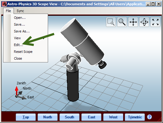
The 3D Scope Editor can be accessed by selecting Edit from the File drop-down menu as shown. For an explanation of other selections in the drop-down menu, refer to the Menu Items section.
Telescope Tab
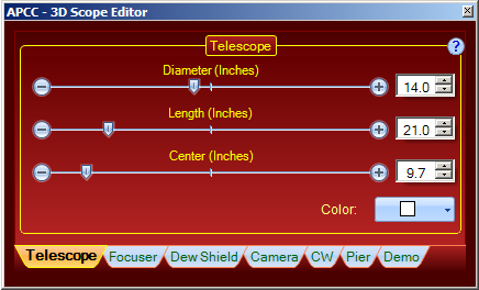
Diameter, Length: Adjust dimensions with slider, arrows or number entry.
Center: Allows you to simulate a balance point of the telescope on the mount by moving the graphical telescope forward or back in relation to the mount.
Color: The drop-down box allows you to change colors. Alas, there is no good representation of Astro-Physics cream white.
Focuser Tab
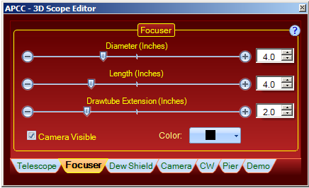
Diameter, Length, Drawtube Extension: Adjust dimensions with slider, arrows or number entry.
Camera Visible: You can specify whether or not the camera should be visible in your graphic. This will impact how your focuser displays.
Color: The drop-down box allows you to change colors.
Dew Shield Tab
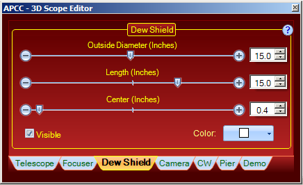
Outside Diameter, Length: Adjust dimensions with slider, arrows or number entry.
Center: Allows you to simulate the position of the dew shield relative to the tube, i.e. whether it is retracted or not.
Visible: Check the box to indicate whether or not the dew shield should be visible.
Color: The drop-down box allows you to change colors. Alas, there is no good representation of Astro-Physics cream white.
Camera Tab
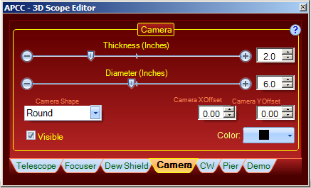
Thickness, Diameter: Adjust dimensions with slider, arrows or number entry.
Camera Shape: Select the closest option from the drop-down list.
Camera x Offset and Camera Y Offset: Use these controls to adjust the camera position.
Visible: Check the box to indicate whether or not the camera should be visible.
Color: The drop-down box allows you to change colors.
CW - Counterweights Tab
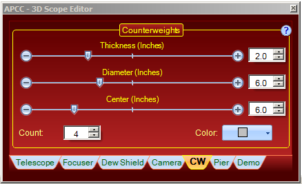
Thickness, Diameter: Adjust dimensions with slider, arrows or number entry.
Center: Adjust the position of the counterweights on the shaft.
Count: Specify the number of counterweights on the shaft.
Color: The drop-down box allows you to change colors.
Pier Tab
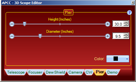
Height, Diameter: Adjust dimensions with slider, arrows or number entry. Consider entering a lower pier height since entry of larger numbers may push the scope out of the view. Unless your telescope is so long it might strike the floor, this is not an important parameter of your setup.
Color: The drop-down box allows you to change colors.
Demo Tab
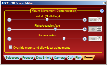
This Demo window allows you to experiment with latitude, RA and Dec values to create a graphic model without actually moving the scope to a particular position. This feature has been useful for us to create graphics.
Override mount and allow local adjustments: Check this box to ignore the input from the mount position data and activate the entry fields. When you are ready to resume your observing session, remember to uncheck this box to resume the input of actual position data.
Latitude, Right Ascension Axis, Declination Axis: Adjust values with slider, arrows or number entry.